Whereas the initial development stages of optical metrology by Klingelnberg were focused on applications used primarily in the lab, the solution now available is systematically oriented toward series application of cylindrical gear measurement. The primary advantage here is greater efficiency through a reduction in measurement times of up to 40 percent.
Optical Gear Measurement: The Next Level
Klingelnberg has systematically advanced optical metrology and has introduced a new white light sensor technology that is ideally suited to measurements in the sub-micrometer range. This will allow the tactile pitch measurement to be replaced by optical measurement, significantly reducing measurement times in serial measurement applications.
Background
Klingelnberg first presented the initial development stage of their hybrid solution with optical metrology at the EMO Hannover exhibition back in 2017. The application at that time centered on digitization of axially symmetrical gear components. Components such as bevel gears and cylindrical gears, and other geometries as well, can thus be measured with an extremely high point density (digitized), followed by additional processing. This additional processing is extremely flexible. In addition to simply depicting the results as a 3D model, comparisons can be made against a CAD target geometry, or a geometrical evaluation can be conducted by creating sectional views. This application is used for reverse engineering, for example.
“In the last three years, we have significantly advanced our Klingelnberg Optical Metrology system,” explains Markus Finkeldey, project manager of Optical Metrology at Klingelnberg. “Particularly in terms of sensor systems, measured data acquisition, and further processing, there has been significant progress.”High Accuracy in the Sub-Micrometer Range
In the first development stage, a high-precision laser triangulation sensor was used. This sensor technology is well suited to the digitization application described above. However, physical limits in laser triangulation restrict its use for measurements in the sub-micrometer range on gear components. “Because tactile gear metrology on the precision measuring centers over the years has achieved an extremely high level of maturity and thus also an impressive measuring accuracy, our customers’ expectations for optical metrology on a Klingelnberg measuring machine are correspondingly high,” notes Peter Mancasola, application engineer at Klingelnberg. “A restriction in accuracy that is accepted for digitization is not acceptable for other measurement tasks.”New White Light Measurement System
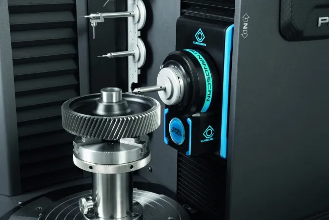
For this reason, Klingelnberg has been focusing its efforts on the entire signal chain in optical metrology and has joined forces with other development partners to develop a white light measurement system tailored specifically to the requirements of gear measurement. In this system, the active, current-carrying elements, such as a high-power light source, electronics and signal processing, are arranged separately from the sensor in the control cabinet. The distinct advantage of this is that it prevents thermal effects from occurring on the sensor itself as well as in the area surrounding the sensor – on the 3D tracer head, for example.
Compared to a laser sensor, this sensor has a significantly more favorable, compact design. In addition, in contrast to a laser sensor, this sensor works equally in all directions due to the coaxial light directed toward the component surface and back. The large lens aperture enables measurements with highly inclined surfaces, which are inevitable occurrences on gearings. Thanks to the system’s high resolution, measurements in the sub-micrometer range are now ensured.
Reducing Measurement Times in Serial Measurement
Digitization of the entire component is an application for which optical metrology is ideally suited. For serial measurement of high-precision ground running gears, however, it is not necessary to measure the entire component geometry with a high point density. Instead, the focus is on high measuring accuracy at the level of the tactile measurement while also reducing the measurement time. For this reason, Klingelnberg has worked out a solution to this with its latest development stage in optical metrology.
Optical sensor retracted
In serial measurement of a cylindrical gear, the profile and lead are typically measured on three or four teeth, and pitch measurement is performed on all teeth. This tactile pitch measurement necessarily involves inserting the stylus into each tooth space. With optical measurement, by contrast, nothing is inserted into the tooth spaces. Accordingly, pitch measurement offers the greatest potential for reducing the measurement time. Through optical measurement of the pitch using one continuous, uninterrupted rotation of the component, the measurement time advantage increases with large numbers of teeth to up to 80 percent. It is not necessary to scan a large area of the gear with multiple revolutions.
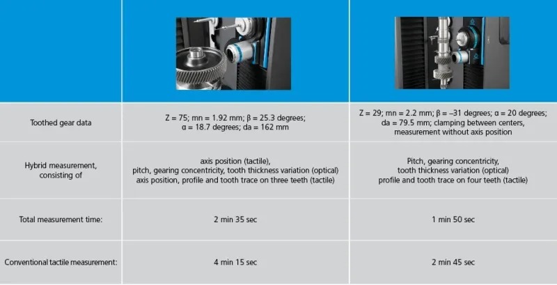
This optical pitch measurement is combined with the tactile measurement of the profile and lead. Overall, the total measurement time decreases by up to 40 percent. Thus in cases where there is a high utilization rate of the measuring machine, the costs for the optical metrology option are quickly recovered.
High-Precision Measuring Results
Decreased measurement time is not the only key factor, however. Just as important is a high achievable accuracy of the measuring results, even in the case of extremely complex gears with ground surfaces and steep profile angles. This is the result of intensive optimization of the sensor technology, the analysis algorithms, and the measurement strategy.
Measurement software user interface
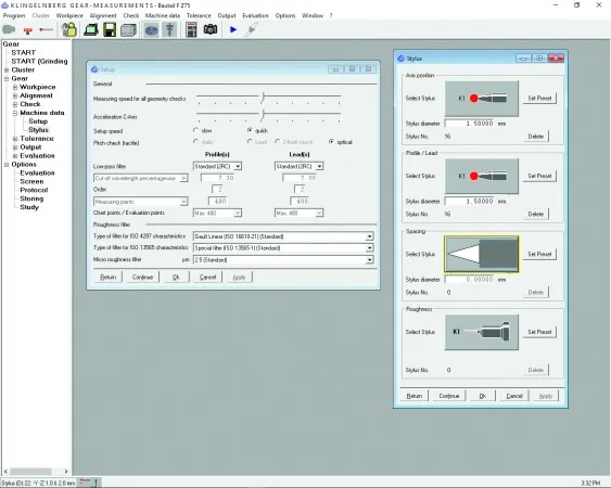
The only difference in operation is that optical pitch measurement must be selected in the same cylindrical gear measurement software customers are already familiar with. The measuring cycle is automatically modified accordingly, and the pitch measurement is performed with the optical sensor. The changeover between the tactile 3D NANOSCAN probing system and the retractable optical HISPEED OPTOSCAN sensor takes place automatically within approximately 1.5 seconds in conjunction with the entire measuring run.
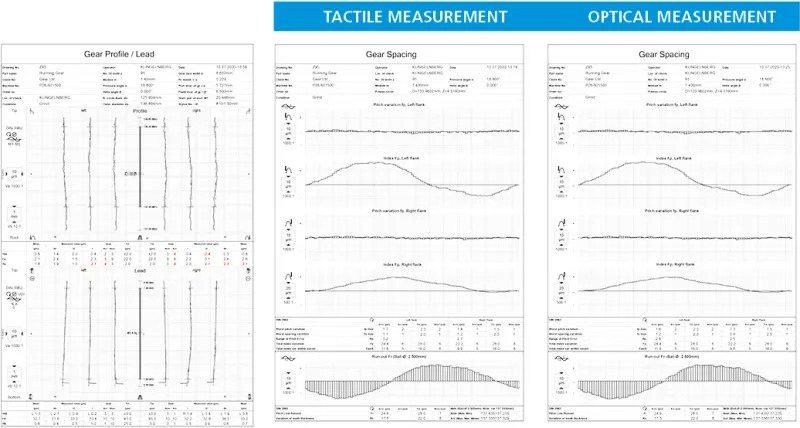
During a series of internal analyses, Klingelnberg evaluated a typical component spectrum of cylindrical gears from the area of passenger car transmissions, electromobility and gauges. In a range of gear geometries with different reflection and absorption characteristics, as well as various gearing qualities, accuracy on par with tactile measurement were achieved. The system can be used even for gears with extremely fine surfaces and roughnesses of Rz = 1 µm.
“To determine without a doubt whether a component is suitable for optical measurement and whether a corresponding measurement time advantage can be achieved, we provide our customers with test measurements and demonstrations in our premises,” says Holger Haybach, Head of Application Engineering at Klingelnberg.
The More, The Better
In terms of the measurement time advantage that can be achieved, one thing is true: The more teeth there are, the greater the advantage. However, even a component with 29 teeth benefits from a significant time advantage, as the examples in the table on the right show.
Measuring results, profile and lead (left) Measuring results, pitch, comparison of tactile and optical (right)Gear Measurement ExamplesNext Development Stages
The system offers great potential for further applications. In particular, for measurement tasks consisting of tactile operations involving time-consuming individual touches and complex movement patterns, optical metrology is able to reduce measurement time. But optical measurement is also ideal for fast scanning sequences on complex geometries.
Dr. Christof Gorgels, Director of Product Line Precision Measuring Centers at Klingelnberg, provides an outlook: “For the further development of the system, we already have a number of ideas, including tooth root and tip measurement, axis position, roundness and other formmeasurement tasks. And we would like to use our customers’ feedback to set priorities. That is why we are delighted at the keen interest in Klingelnberg Optical Metrology and the conversations with users that we have had as a result.”
For more information: www.klingelnberg.com

 Tiếng Việt
 Tiếng Anh
 Tiếng Hàn
 Tiếng Trung
 High Accuracy in the Sub-Micrometer Range
In the first development stage, a high-precision laser triangulation sensor was used. This sensor technology is well suited to the digitization application described above. However, physical limits in laser triangulation restrict its use for measurements in the sub-micrometer range on gear components. “Because tactile gear metrology on the precision measuring centers over the years has achieved an extremely high level of maturity and thus also an impressive measuring accuracy, our customers’ expectations for optical metrology on a Klingelnberg measuring machine are correspondingly high,” notes Peter Mancasola, application engineer at Klingelnberg. “A restriction in accuracy that is accepted for digitization is not acceptable for other measurement tasks.”
New White Light Measurement System
For this reason, Klingelnberg has been focusing its efforts on the entire signal chain in optical metrology and has joined forces with other development partners to develop a white light measurement system tailored specifically to the requirements of gear measurement. In this system, the active, current-carrying elements, such as a high-power light source, electronics and signal processing, are arranged separately from the sensor in the control cabinet. The distinct advantage of this is that it prevents thermal effects from occurring on the sensor itself as well as in the area surrounding the sensor – on the 3D tracer head, for example.
High Accuracy in the Sub-Micrometer Range
In the first development stage, a high-precision laser triangulation sensor was used. This sensor technology is well suited to the digitization application described above. However, physical limits in laser triangulation restrict its use for measurements in the sub-micrometer range on gear components. “Because tactile gear metrology on the precision measuring centers over the years has achieved an extremely high level of maturity and thus also an impressive measuring accuracy, our customers’ expectations for optical metrology on a Klingelnberg measuring machine are correspondingly high,” notes Peter Mancasola, application engineer at Klingelnberg. “A restriction in accuracy that is accepted for digitization is not acceptable for other measurement tasks.”
New White Light Measurement System
For this reason, Klingelnberg has been focusing its efforts on the entire signal chain in optical metrology and has joined forces with other development partners to develop a white light measurement system tailored specifically to the requirements of gear measurement. In this system, the active, current-carrying elements, such as a high-power light source, electronics and signal processing, are arranged separately from the sensor in the control cabinet. The distinct advantage of this is that it prevents thermal effects from occurring on the sensor itself as well as in the area surrounding the sensor – on the 3D tracer head, for example.
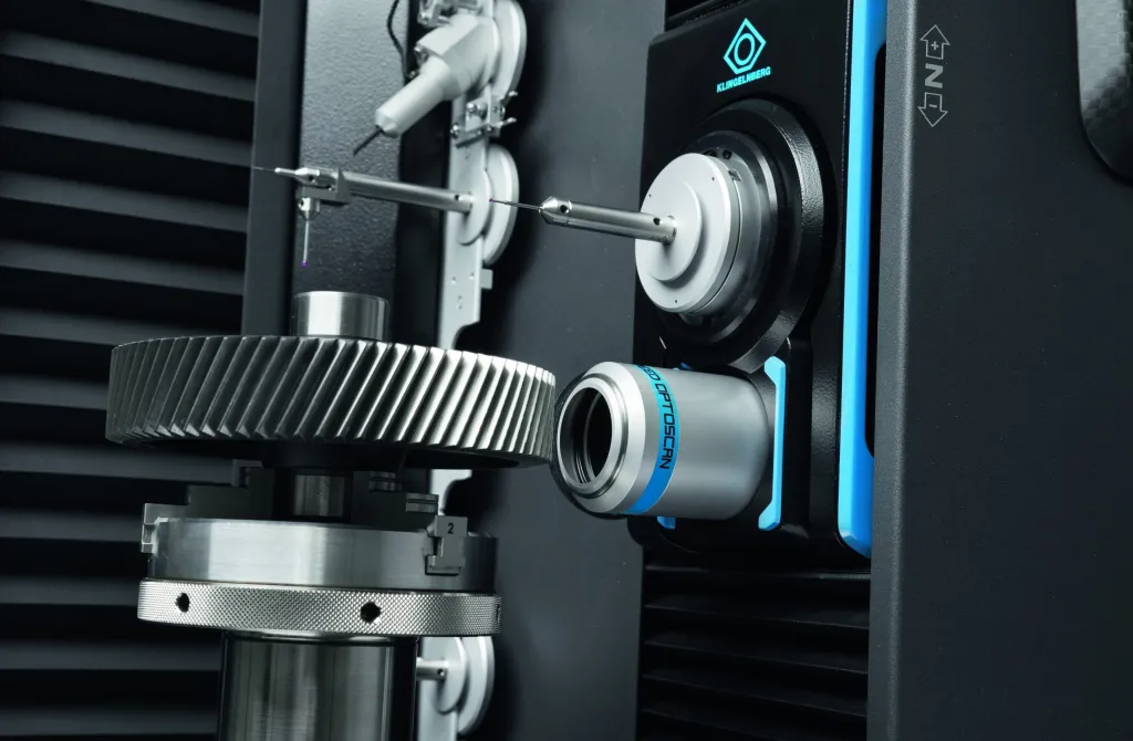 Compared to a laser sensor, this sensor has a significantly more favorable, compact design. In addition, in contrast to a laser sensor, this sensor works equally in all directions due to the coaxial light directed toward the component surface and back. The large lens aperture enables measurements with highly inclined surfaces, which are inevitable occurrences on gearings. Thanks to the system’s high resolution, measurements in the sub-micrometer range are now ensured.
Reducing Measurement Times in Serial Measurement
Digitization of the entire component is an application for which optical metrology is ideally suited. For serial measurement of high-precision ground running gears, however, it is not necessary to measure the entire component geometry with a high point density. Instead, the focus is on high measuring accuracy at the level of the tactile measurement while also reducing the measurement time. For this reason, Klingelnberg has worked out a solution to this with its latest development stage in optical metrology.
Compared to a laser sensor, this sensor has a significantly more favorable, compact design. In addition, in contrast to a laser sensor, this sensor works equally in all directions due to the coaxial light directed toward the component surface and back. The large lens aperture enables measurements with highly inclined surfaces, which are inevitable occurrences on gearings. Thanks to the system’s high resolution, measurements in the sub-micrometer range are now ensured.
Reducing Measurement Times in Serial Measurement
Digitization of the entire component is an application for which optical metrology is ideally suited. For serial measurement of high-precision ground running gears, however, it is not necessary to measure the entire component geometry with a high point density. Instead, the focus is on high measuring accuracy at the level of the tactile measurement while also reducing the measurement time. For this reason, Klingelnberg has worked out a solution to this with its latest development stage in optical metrology.