In the same way that the primary survey network
established in 2010 on site provided a global coordinate system for civil engineering works and the positioning of the buildings, the ITER metrology team has now developed a vast matrix of reference ‘targets,’ or fixed points, inside the Tokamak Complex for use in measuring and aligning tokamak components and systems.
These points are ‘materialized’ by small magnetic discs called fiducial nests installed by European contractors inside the buildings. The nests are used to receive spherically mounted reflectors (SMRs), which are surveyed with laser trackers to establish their coordinate values and confirm their compliance with the simulation used during the network design process.
This in-building network of reference points will represent the physical realization of the Tokamak Global Coordinate System (TGCS). “
From any location in the Tokamak Complex, this coordinate system can be accessed by measuring a small number of reference points local to the measurement task. This is a powerful—and absolutely essential—tool for our installation contractors,” says Lionel Poncet, metrology engineer within the Tokamak Assembly Division.
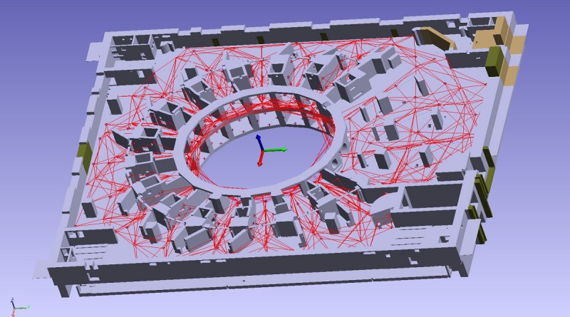 A vast network of fiducial target nests installed on the concrete surfaces of the bioshield, port cells and galleries will enable installation contractors to align components to sub-millimetre accuracy. Advanced software was used to lay out the positions of each instrument station and simulate clear lines of sight to the fiducial nests. This simulated measurement geometry was used to predict the measurement uncertainty to be expected, which was subsequently qualified with real measurement data.
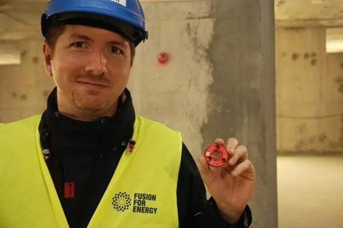 Giacomo Calchi from the Fusion for Energy metrology team, shows the size of fiducial target nest – one of 2,000 to be installed inside of the Tokamak Complex. © F4E
Giacomo Calchi from the Fusion for Energy metrology team, shows us the size of a fiducial target nest. one of 2,000 to be installed inside of the Tokamak Complex.
Starting from detailed CAD (computer-aided design) data for the buildings, the team used specialized SpatialAnalyzer software, from
New River Kinematics, to design and simulate the in-building matrix, establishing the exact location of each instrument station and plotting fiducial nests with clear lines of sight. A large number of stations and nests were planned as a way to reduce the uncertainty in the calculations.
“We are using advanced software tools that allow the many lines of sight from the collection of instruments to be ‘bundled’ and ‘weighted’—an analytic capability that actually permits us to optimize measurement geometries and minimize uncertainty to design values,” says Poncet.
The accuracy of the network has been measured within a global uncertainty range of 0.2 to 0.4 mm, allowing installation contractors to align components to sub-millimetre accuracy.
European contractors are using data from the ITER Organization to install the fiducial nests progressively, beginning with the lower levels of the Tokamak Complex and moving up. The consistency, with the design, of the targets installed to date, approximately 1,000 out of 2,000, has been confirmed and their measured coordinates are about to be released for use by contractors.
“This collaboration between the European Domestic Agency (Fusion for Energy) and the ITER Organization has proven extremely efficient and cost effective, ensuring continuity of the dimensional control process and providing independent qualification by the two metrology teams,” says Dave Wilson, Metrology Group Leader for ITER.
Currently the network is providing the reference frame for surveys of the as-built position of approximately 100,000
embedded plates by European contractors. Later this month, it will be used by an ITER contractor for the installation of the first machine component (
a feeder segment) in the Tokamak assembly pit.
For more information:
www.iter.org

 Tiếng Việt
 Tiếng Anh
 Tiếng Hàn
 Tiếng Trung