Calibration Method Enables Microscopes to Make Accurate 3D Measurements
Conventional microscopes provide essential information about samples in two dimensions — the plane of the microscope slide. But flat is not all that. In many instances, information about the object in the third dimension — the axis perpendicular to the microscope slide — is just as important to measure.
Now researchers at the National Institute of Standards and Technology (NIST) have found a way to convert a problem affecting nearly all optical microscopes — lens aberrations, which cause imperfect focusing of light — into a solution that enables conventional microscopes to accurately measure the positions of points of light on a sample in all three dimensions.
Although other methods have enabled microscopes to provide detailed information about three-dimensional structure, these strategies have tended to be expensive or require specialized knowledge. In one previous approach to measuring positions in the third dimension, researchers altered the optics of microscopes, for instance by adding extra astigmatism to the lenses. Such alterations often required reengineering and recalibration of the optical microscope after it left the factory.
The new measurement method also enables microscopes to more accurately and precisely locate the positions of objects. Optical microscopes typically resolve the positions of objects to a region no smaller than a few hundred nanometers (billionths of a meter), a limit set by the wavelength of the light that makes the image and the resolving power of the microscope lenses. With the new technique, conventional microscopes can pinpoint the positions of individual light-emitting particles within a region one-hundredth as small.
NIST researchers Samuel Stavis, Craig Copeland and their colleagues described their work in the June 24 issue of Nature Communications.
The method relies on a careful analysis of images of fluorescent particles that the researchers deposited on flat silicon wafers for calibration of their microscope. Due to lens aberrations, as the microscope moved up and down by specific increments along the vertical axis — the third dimension — the images appeared lopsided and the shapes and positions of the particles appeared to change. The NIST researchers found that the aberrations can produce large distortions in images even if the microscope moves just a few micrometers (millionths of a meter) in the lateral plane or a few tens of nanometers in the vertical dimension.
The analysis enabled the researchers to model exactly how the lens aberrations altered the appearance and apparent location of the fluorescent particles with changes in the vertical position. By carefully calibrating the changing appearance and apparent location of a particle to its vertical position, the team succeeded in using the microscope to accurately measure positions in all three dimensions.
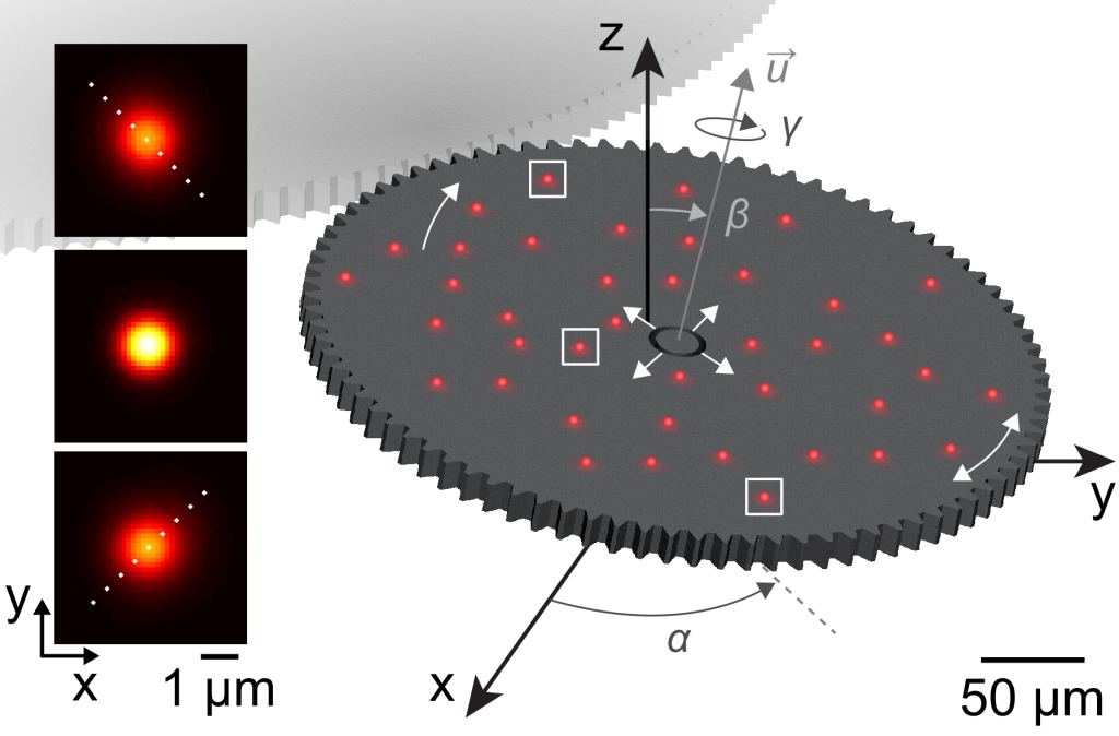
Left: Images of fluorescent particles that are above, at and below (top to bottom) the vertical position of best focus of a microscope. Calibrating the effects of lens aberrations on the apparent shape and position of the particle images enables accurate measurement of the position in all three spatial dimensions using an ordinary optical microscope. Right: Tracking and combining information from many fluorescent particles on a tiny rotating gear tests the results of the new calibration and elucidates the motion of a complex microsystem in all three dimensions.“Counterintuitively, lens aberrations limit accuracy in two dimensions and enable accuracy in three dimensions,” said Stavis. “In this way, our study changes the perspective of the dimensionality of optical microscope images, and reveals the potential of ordinary microscopes to make extraordinary measurements.”
Using the latent information provided by lens aberrations complements the less accessible methods that microscopists currently employ to make measurements in the third dimension, Stavis noted. The new method has the potential to broaden the availability of such measurements.
The scientists tested their calibration method by using the microscope to image a constellation of fluorescent particles deposited randomly on a microscopic silicon gear that rotated in all three dimensions. The researchers showed that their model accurately corrected for the lens aberrations, enabling the microscope to provide full three-dimensional information about the position of the particles.
The researchers were then able to extend their position measurements to capture the entire range of motion of the gear, including its rotating, wobbling and rocking, completing the extraction of spatial information from the system. These new measurements highlighted the consequences of nanoscale gaps between microsystem parts, which varied due to imperfections in the fabrication of the system. Just as a loose bearing on a wheel causes it to wobble, the study showed that the nanoscale gaps between parts not only degraded the precision of the intentional rotation, but also caused unintentional wobbling, rocking and even flexing of the gear, all of which could limit its performance and reliability.
Microscopy laboratories could easily implement the new method, Copeland said. “The user just needs a standard sample to measure their effects and a calibration to use the resulting data,” added Stavis. Aside from the fluorescent particles or a similar standard, which already exist or are emerging, no extra equipment is needed. The new journal article includes demonstration software that guides researchers in how to apply the calibration.
Paper: Craig R. Copeland, Craig D. McGray, B. Robert Ilic, Jon Geist and Samuel M. Stavis. Accurate localization microscopy by intrinsic aberration calibration. Nature Communications. June 24, 2021. DOI: 10.1038/s41467-021-23419-y
For more information: www.nist.gov

 Tiếng Việt
 Tiếng Anh
 Tiếng Hàn
 Tiếng Trung